Closed Loop Transfer Function Matlab
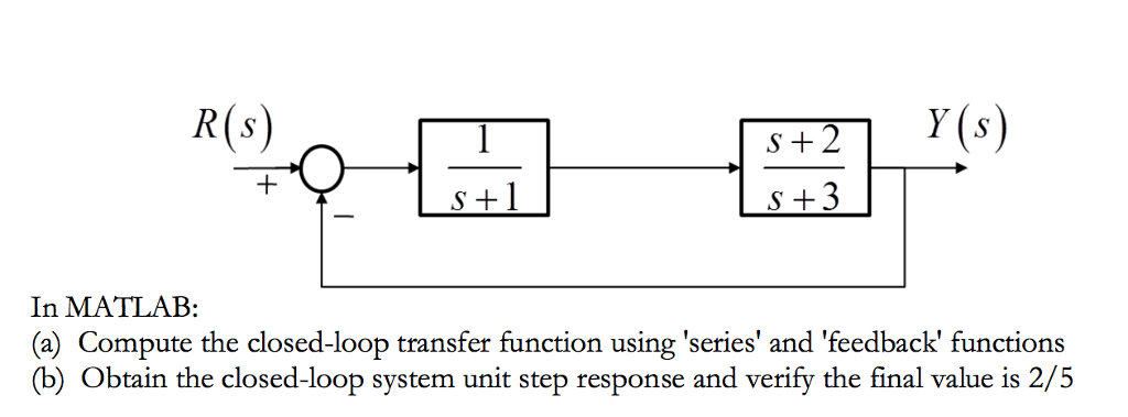
Solved In Matlab A Compute The Closed Loop Transfer Fun Chegg Com
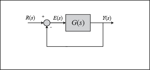
Control Tutorials For Matlab And Simulink Extras Steady State Error
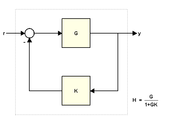
Using Feedback To Close Feedback Loops Matlab Simulink Example

Closed Loop Transfer Function From Generalized Model Of Control System Matlab Getiotransfer Mathworks Italia

Find Closed Loop Transfer Function From The Open Loop Transfer Function For A Unity Feedback
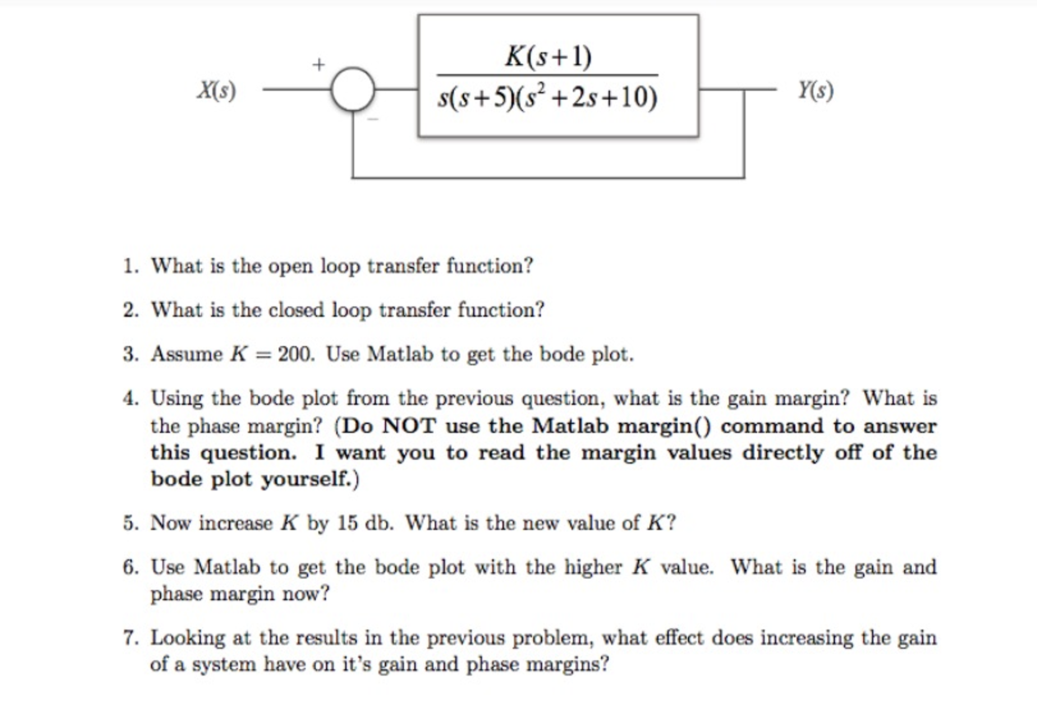
Solved What Is The Open Loop Transfer Function What Is T Chegg Com

You can add a controller and compute the closed loop transfer function.
Closed loop transfer function matlab.
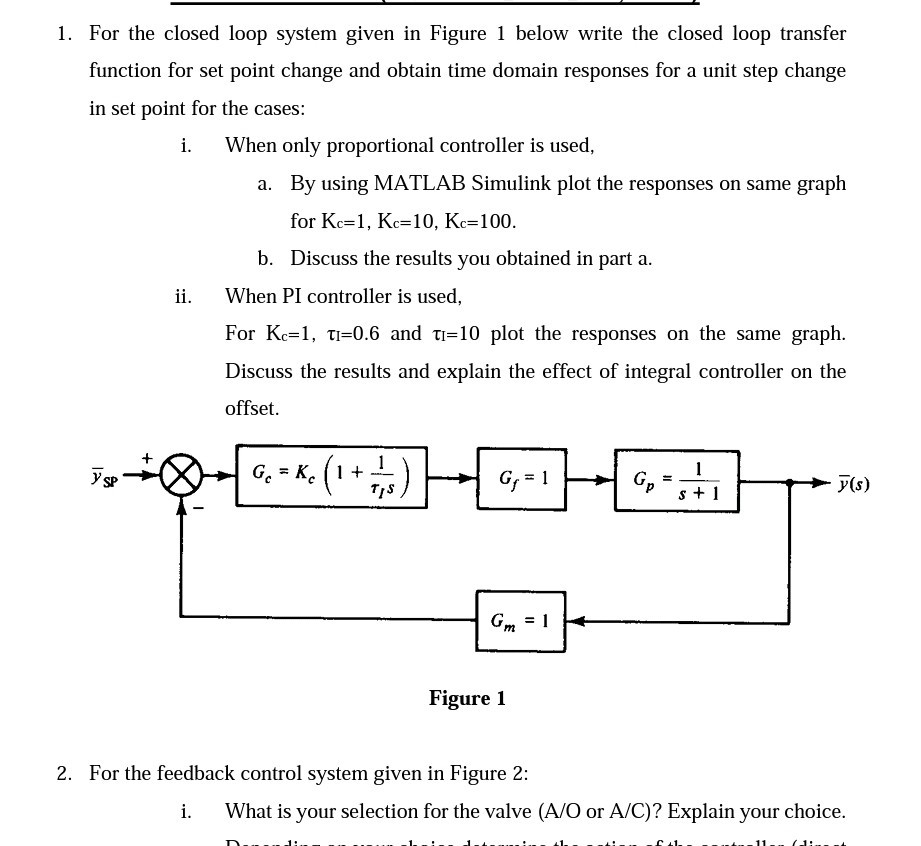
1 For The Closed Loop System Given In Figure 1 Be Chegg Com
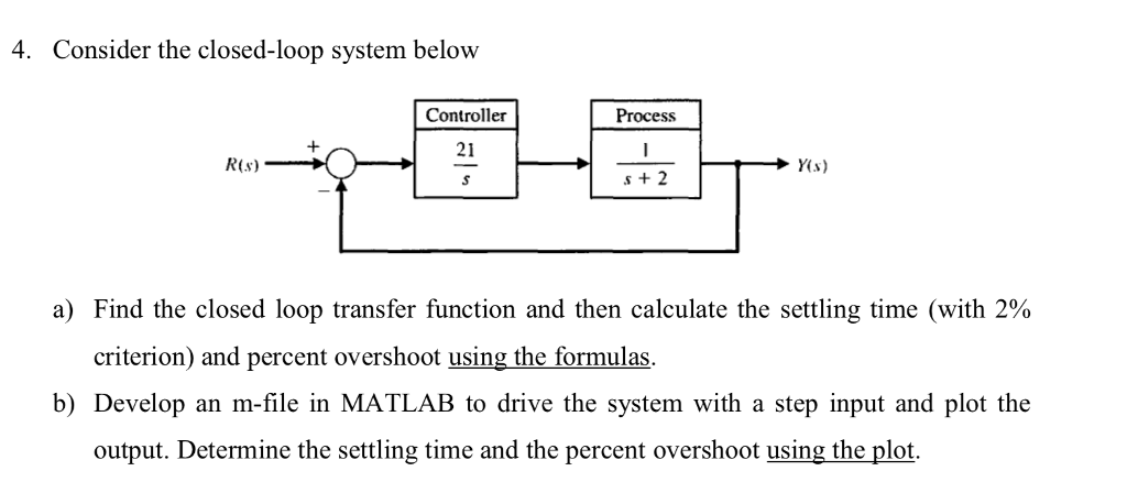
Solved A Find The Closed Loop Transfer Function And Then Chegg Com

Control Tutorials For Matlab And Simulink Motor Position Digital Controller Design
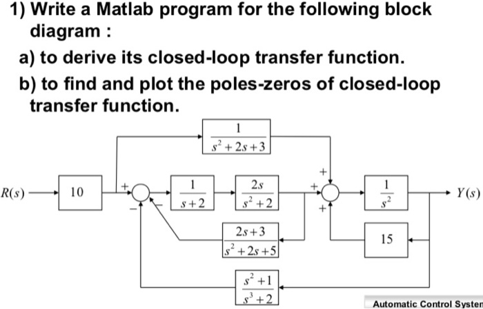
Solved 1 Write A Matlab Program For The Following Block Chegg Com
Source : pinterest.com
